Let’s say you need a specific shape for your modeler and this shape is directly available , you can create an SVG file (or a PNG one …) and use it as a shape. It’s fairly easy to leverage Inkscape and define your shape with it :
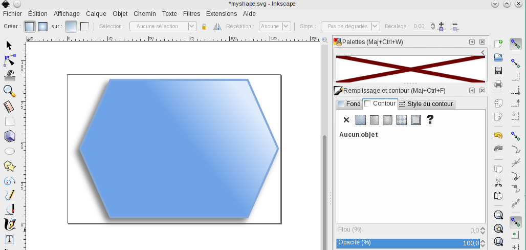
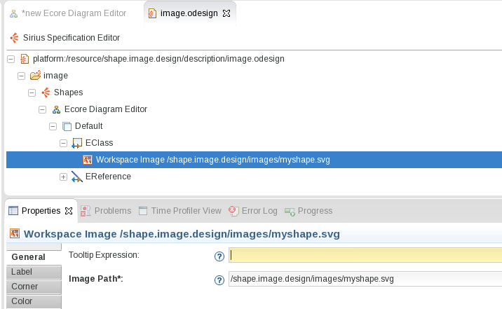
Then just specify the path to this SVG file and you’re done.
And here is the result :
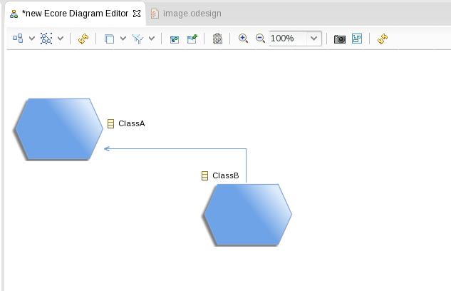
Problem is whatever the shape you use, for the Sirius runtime it is an image and as such a rectangle. That makes edges anchors not touching the actual border of the shape (which is within the image) and the end user of the modeler have no idea why !
You could always extend Sirius with some specific code to explicitely define the anchors but it means you have to plug into GMF’s extension points and it is non trivial compared to what you can do in the .odesign.
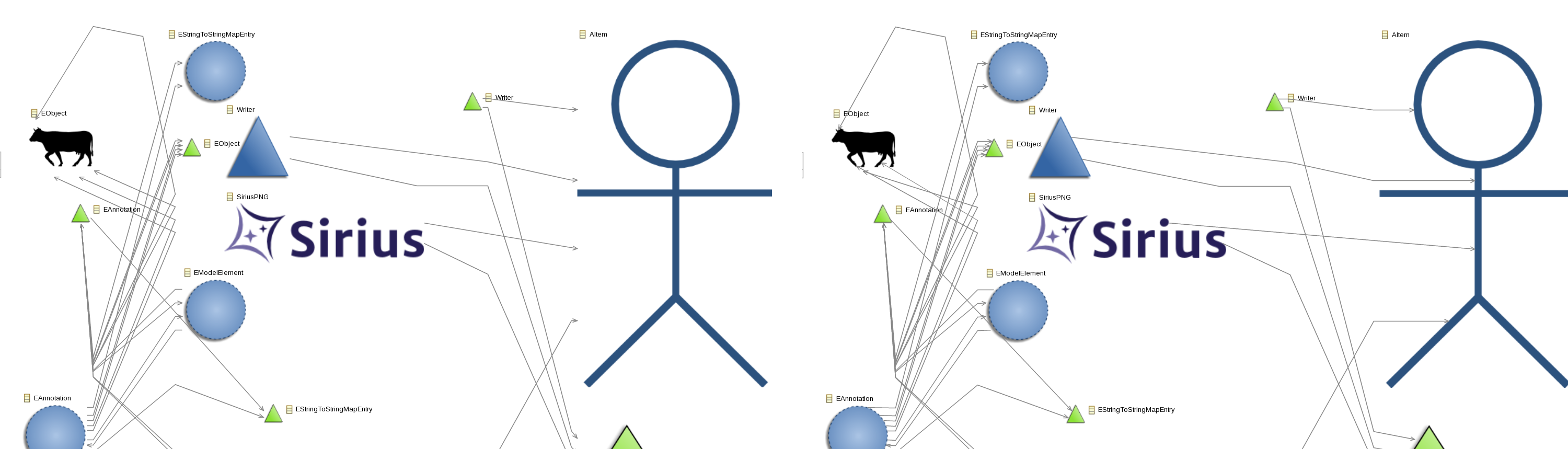
Starting with Sirius 3.0.0M6 we extended the algorithm to shift the anchors position depending on the image content. Transparents pixels are not considered as being part of the shape giving a cleaner result by default :

The image now behave just like a native shape. Here is a previous/after capture, cleaner isn’t it ?